Thermoforming is widely recognized for producing shallow to moderate-depth parts with excellent efficiency. Deep-draw plastic molding extends that capability, opening up opportunities to manufacture larger three-dimensional components with more complex geometry and integrated features.
As part depth increases, the forming process becomes more sensitive to design variables—particularly when draw depth approaches or exceeds the object’s smallest horizontal dimension. Under these conditions, material stretch, wall thickness distribution, and cooling behavior must be carefully managed to deliver consistent results.
This guide outlines the key engineering considerations involved in high draw-ratio projects. Whether you are new to the process or already familiar with component architecture, the Deep-Draw Thermoforming Guide for Engineers offers a reference for developing parts that perform reliably from the first production run through full-scale manufacturing.
Why Deep Draw Projects Carry Higher Design Risk
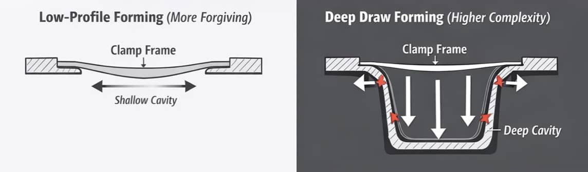
Low-profile components are relatively forgiving. Material stretches modestly, wall thinning remains predictable, and stresses stay within manageable limits. Parts such as trays, panels, covers, and light-duty enclosures allow a fair amount of design flexibility without drastically affecting manufacturability.
Deep-draw thermoforming involves a more demanding set of dynamics. The primary challenge occurs as the polymer is pulled farther from the clamp frame into a deep cavity, forcing the sheet to stretch across greater distances. This intensifies several variables, including:
- Non-uniform gauge reduction in deeper sections
- Corner stresses concentrating around smaller radii or abrupt geometric transitions
- Polymer memory affecting post-form relaxation
- Cooling variations impacting dimensional stability and shrinkage behavior
When these factors are accounted for early on, the expanded forming range of deep-draw implementations can be leveraged, enabling features—such as structural ribs, recessed bosses, and mounting points—that enhance utility.
Core DFM Rules for Deep Draw Thermoforming
Incorporating design for manufacturability (DFM) principles before finalizing CAD geometry facilitates a smooth transition from concept to production. Outlined below are established industry practices for high draw builds. When applied correctly, they improve forming consistency, strengthen structural integrity, and help manage costs and cycle times.
1. Tooling and Engineering Collaboration
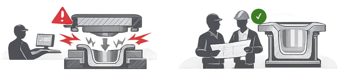
Deep-draw design requires systematic refinement before manufacturing begins. When part configuration, engineering, and tooling development occur in isolation, small issues can quickly escalate into extended redesigns and costly delays.
In deep-draw scenarios, tooling significantly affects how thermoplastics stretch, flow, and cool. In many cases, failures originate prior to a mold being built, where seemingly minor geometry decisions can cause substantial downstream consequences.
A well-coordinated tooling process helps identify potential challenges before molds are fabricated.
2. Draw Ratio Management
Managing draw ratio is crucial for predicting stretching demands and selecting an appropriate starting sheet thickness.
The draw ratio is typically calculated as the surface area of the formed part divided by the footprint area of the original heated sheet (or mold opening area). This ratio indicates the overall stretch required for the project.
The diagram below lists practical draw ratio guidelines.
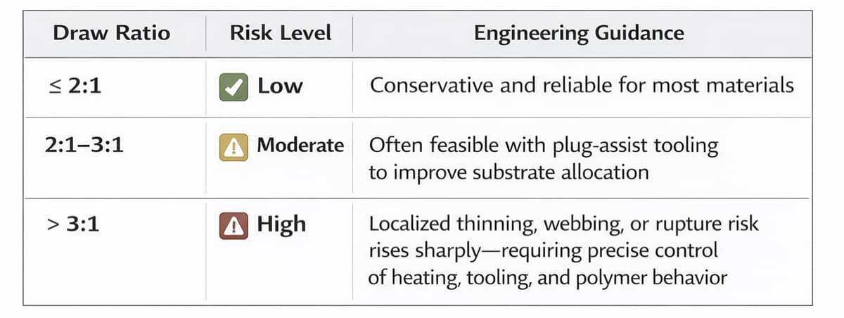
Intricate features—such as tall sidewalls combined with ribs, recessed bosses, and tight internal spaces—can create localized high-stretch regions. These areas should be evaluated during initial design reviews, and solutions such as staged forming or plug-assist tooling may be needed to maintain balanced material spread.
3. Material Selection and Stretch Considerations
Material choice plays a fundamental role in a job’s success, as polymer characteristics largely determine how the heated sheet stretches when drawn over—rather than into—the mold surface.
When polymer is pushed beyond its limits, wall thinning can concentrate near bottom radii and deep corners, where the sheet travels the farthest distance. Uneven cooling or shrinkage behavior may also introduce internal stresses that contribute to post-form warping or dimensional variation.
Different thermoplastics respond differently during forming:
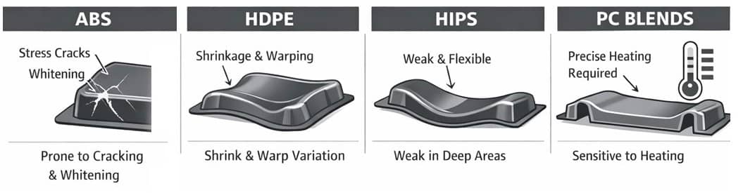
Aligning polymer properties with component depths, structural needs, service environment, and tolerance expectations contribute to ensuring stable molding conditions and consistent thickness across production runs.
4. Draft Angles
Adequate draft is essential for reducing friction between the heated sheet and the mold surface in order for the formed part to release cleanly from the tool.
For most resins, a minimum of 1.5 to 3° per side is standard for female (negative) molds. Male (positive) molds often require 3 to 7°, with 4 to 6° recommended. Mold surfaces with textured finishes commonly require 5° or greater draft to prevent scuffing or drag marks.
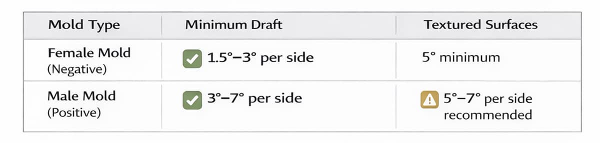
As draw depth increases, the contact area between the sheet and mold also increases—making sufficient draft progressively more important to prevent distortion, surface damage, or ejection issues.
5. Radii and Corner Design
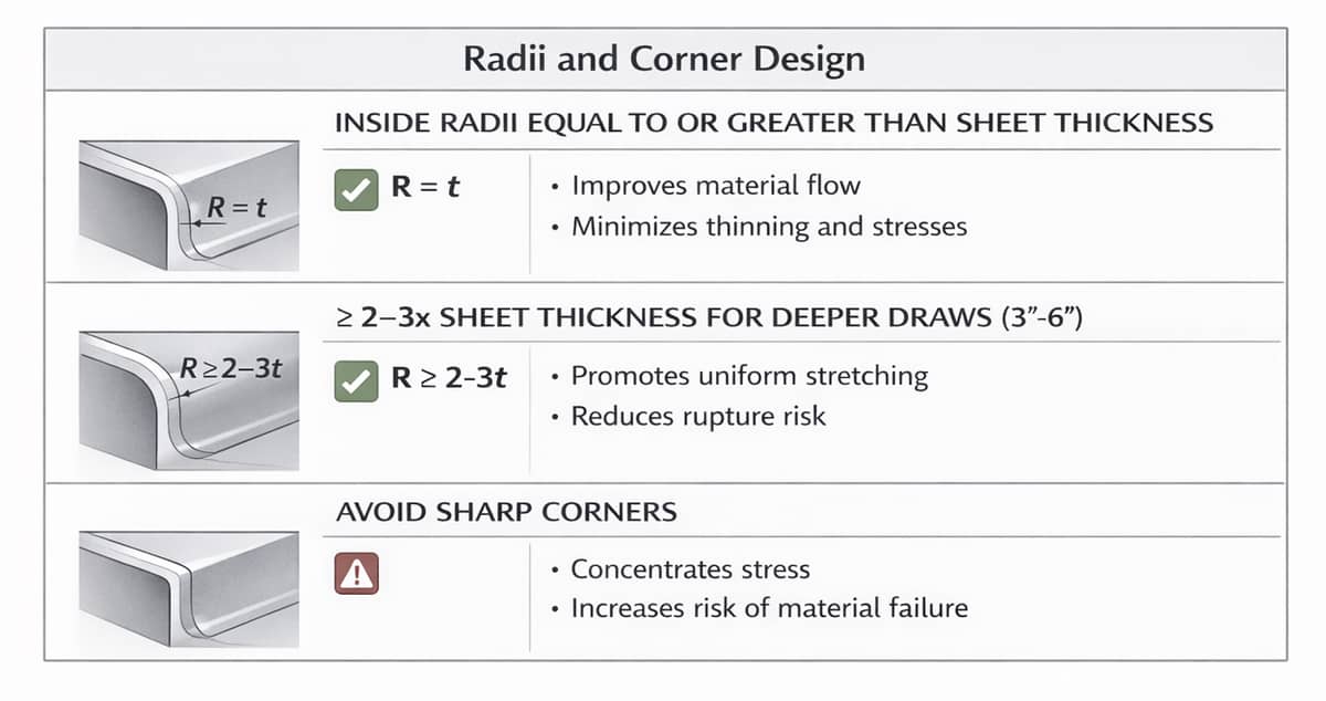
Corner geometry is a primary driver of material spread, as sharp corners can cause localized gauge reduction and stress accumulation. Inside radii equal to or greater than the sheet thickness help prevent these issues.
In deeper draws, radii in the range of two to three times the polymer thickness—or roughly 0.125” to 0.250” for draw depths of 3” to 6”—promote smoother flow and homogeneous wall distribution.
Larger radii distribute stretch more uniformly, reducing the risk of cracking and providing better support for nearby structural elements without weakening adjacent walls.
6. Wall Thickness Uniformity
Uniform wall design is one of the most important—and often overlooked—DFM principles. Final wall thickness is largely governed by substrate distribution during forming.
When component shape forces uneven stretching, certain areas may thin excessively while others retain more material, which compromises strength and stability.
An effective engineering approach encompasses the following:
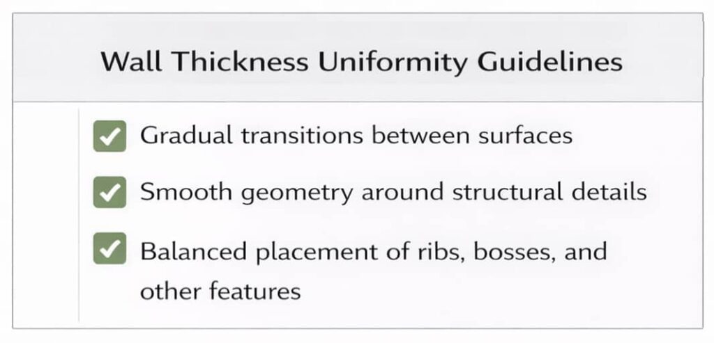
If geometry supports these conditions, consistent minimums and repeatable structural performance can be attained.
7. Undercuts and Complex Features
Undercuts—recessed or overhanging features with negative draft—can add valuable functionality and rigidity, enabling geometries such as snap-fits, hidden edges, and locating surfaces.
However, they complicate tooling. For example, parts with undercuts cannot be released using a simple straight-pull mold and therefore often require movable sections, collapsible cores, loose inserts, or split tooling. These mechanisms elevate tooling complexity, extend cycle times, raise labor requirements, and add to overall cost.
For this reason, undercuts should be avoided whenever possible. When their inclusion is necessary, they should remain shallow, adequately drafted, and accounted for in draw-ratio calculations.
In some cases, secondary operations—such as 5-axis CNC trimming —can achieve the same functional results while allowing simpler, lower-cost tooling.
DFM Summary
Successful deep-draw molding relies on the disciplined management of the seven principles discussed above. When these elements are addressed, manufacturers can unlock the benefits of deep-draw forming while minimizing production challenges.
How Deep Draw Applications Compare to Other Manufacturing Methods
Large part thermoforming—encompassing deep-draw plastic molding—offers clear advantages when manufacturing housings, panels, shrouds, and structural covers, particularly for medium production volumes.
Compared with injection molding, it requires significantly lower tooling investment—often 70–90% less for substantially sized components—allowing manufacturers to move into production more quickly and economically.
Thermoforming also compares favorably with fiberglass fabrication. Although fiberglass can accommodate large geometries, the process is more labor intensive, involves slower cycle times, and introduces greater variability between parts. Thermoformed structures are often 30% or more lighter, with improved surface finish uniformity and broader material options for chemical resistance.
Delivering Deep Draw Parts with Confidence
Prioritizing design for manufacturability principles and working with an experienced manufacturer equipped for large-format thermoforming enables engineers to streamline development and move complex components to production with greater confidence.
At GPI, we specialize in turning challenging deep-draw concepts into reliable components. With advanced equipment, knowledgeable tooling support, and oversized capabilities, we manufacture deep-draw thermoformed parts up to 96″ × 48″—delivering the scale, consistency, and expertise required for demanding applications.